
Tda7294 Subwoofer Amplifier Circuit Diagram Free Download Amplifier Circuit Wiring Diagram
By circuit diagram 3 Comments This is the 300W RMS stereo power amplifier circuit project. This amplifier is based four pieces of power IC TDA7294. It's mean that every single channel of the circuit uses two ICs in bridge mode. In this application, the load value must not be less than 8 Ohms. The main advantages of this solution are the following:
Tda7294 Amplifier Circuit Pcb Wiring Diagram
Description. The TDA7294 is a monolithic integrated circuit in Multiwatt15 package, intended for use as audio class AB amplifier in Hi-Fi field applications (Home Stereo, self powered loudspeakers, Topclass TV). Thanks to the wide voltage range and to the high out current capability it is able to supply the highest power into both 4Ω and 8Ω.
Tda7294 Amplifier Circuit Diagram
The 170W Bridge Amplifier using TDA7294 IC is a powerful amplifier chip that delivers 170 watts of power. The amplifier has a sensitivity of 0.775V, and a signal-to-noise ratio of 100dB. The amplifier circuit includes a potentiometer, which allows the user to adjust the volume of the output audio. The potentiometer is a three-terminal device.
Tda7294 Subwoofer Schematic Circuit Diagram Images
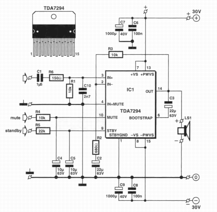
Circuit Diagram of 120W Power Amplifier TDA7294 This amplifier can be designed using a few basic components. The circuit diagram of this project is shown below. 120W Power Amplifier TDA7294 Circuit Diagram Components List of 120W Power Amplifier TDA7294 TDA7294 IC x 1 10uF Capacitor x 2 22uF Capacitor x 2 1000uF Capacitor x 2 470nF Capacitor x 1

Tda7294 Amplifier Circuit Diagram Pdf Tda7294 Based Power Amplifier Circuit Design This
An audio amplifier is a circuit that transforms the small amplitude of audio input signals into a large amplitude audio signal at the output. The basic example of the audio amplifier is the mic circuit. This article is about making an audio amplifier using TDA7294 IC. It is designed as a class AB amplifier. It has great ripple rejection.

Make TDA7294 100W Amplifier Without PCB Hindi You Like Electronic YouTube
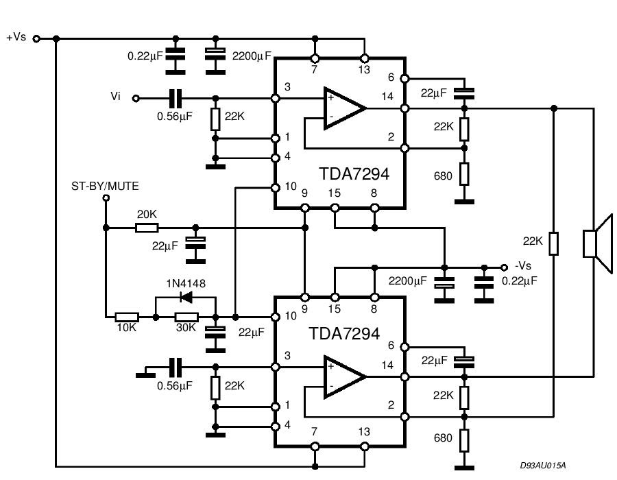
The TDA7294 IC is a popular sound amplifier IC with low cost that has a ton of power handling capacity, 100W to be exact. For this tutorial, we are going to use two of those TDA7294 ICs in a bridge configuration to build an even more powerful amp that can handle up to 170W of RMS power.

Tda7294 Ic Circuit Diagram
TDA7294 DMOS Audio Amplifier. TDA7294 is a monolithic class AB audio amplifier with a DMOS output stage. Firstly, it is used in Hi-Fi field applications for amplification of audio signals which includes self-powered loudspeakers, TV, etc. Secondly, it has its own fault protection circuitry against short-circuits and provides a thermal shutdown.

TDA7294 Circuit Power Amplifier Dynamic 180W Xtronic
MULTIPOWER BCD TECHNOLOGY 1/16 BLOCK DIAGRAM ABSOLUTE MAXIMUM RATINGS Symbol Parameter Value Unit VSSupply Voltage (No Signal) ±50 V IOOutput Peak Current 10 A PtotPower Dissipation Tcase=70°C50W TopOperating Ambient Temperature Range 0 to 70 °C Tstg,TjStorage and Junction Temperature 150 °C TAB connected to -VS PIN CONNECTION (Topview) TDA7294
Tda7294 Amplifier Circuit Diagram
IC TDA 7294. IC TDA7294- 100W DMOS audio amplifier is a monolithic integrated circuit, it comes in multiwatt15V and multiwatt15H packages with a mute option from ST. As IC has mute and stand-by functions to mute the audio output the pin 10 (Vm) should be less than 1.5V and the mute pin 10 (Vm) should be greater than 3.5V.
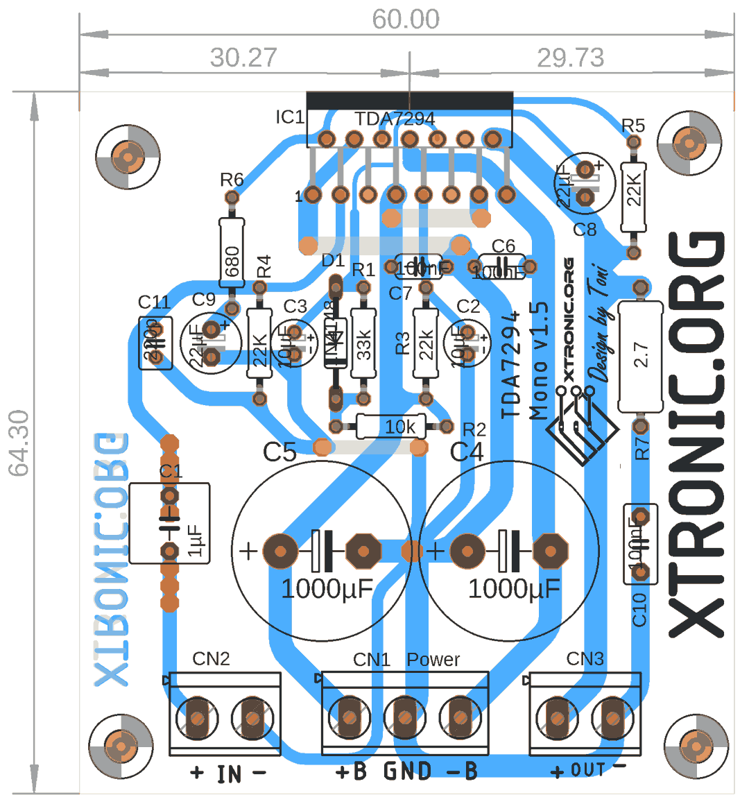
TDA7294 Amplifier Circuit Diagram PCB Xtronic
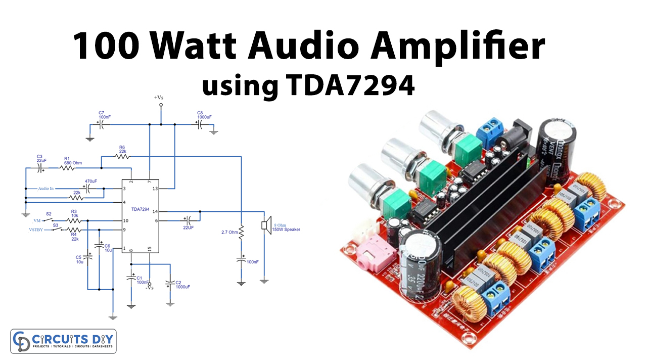
Working Explanation. The TDA7294 Subwoofer Amplifier Circuit uses the IC having 15pins. VM represents the mute ON and OFF voltages, which are 1.5V and 3.5V respectively in the circuit. The standby ON and OFF voltages are 1.5 volts and 3.5 volts, respectively, in VSTBY. We attach the input coupling capacitor C8 to the non-inverting pin of the IC.

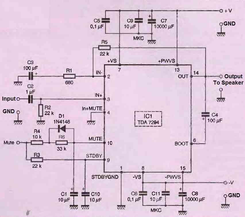
TDA7294 100W integrated LF amplifier, schematic and specifications
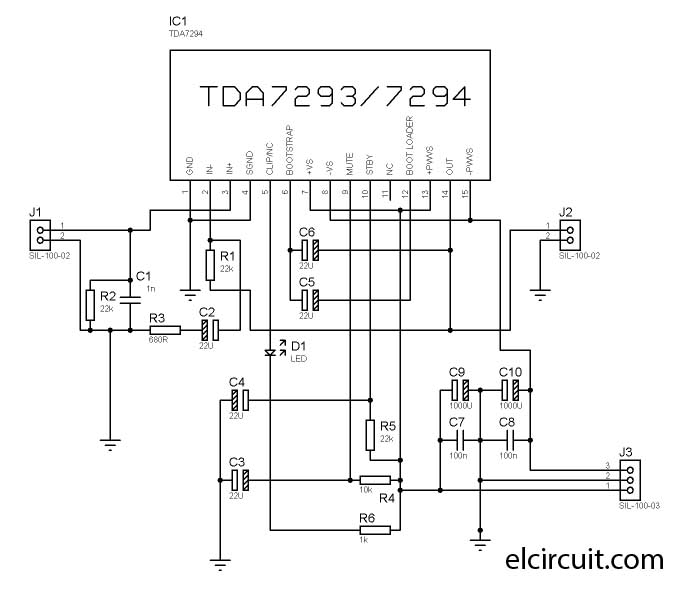
This amplifier requires a 24-0-24/5-10A symmetrical transformer. For those who want to download the complete file, you can download it here: Schematic and PCB Layout of the TDA7294 2.1 Amplifier. layout and schematic of a power amplifier with a 2.1 Channel Amplifier system that uses an IC. The IC used is the TDA7294 IC. Because this Amplifier i
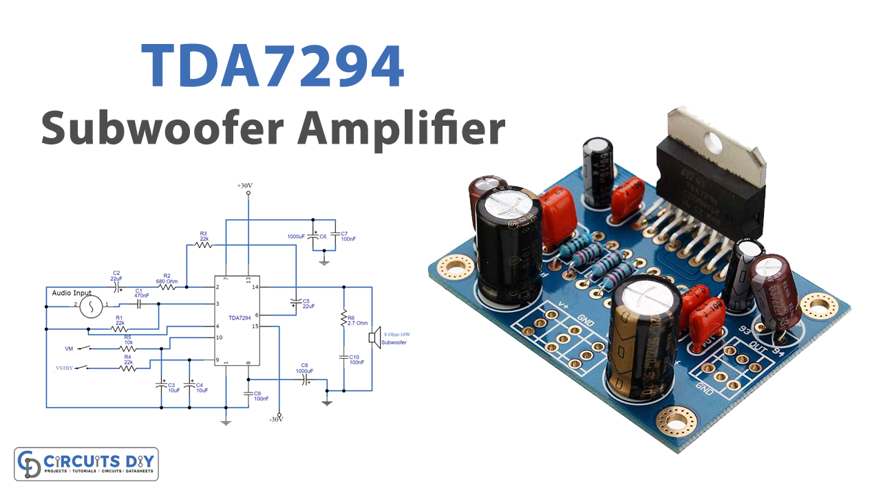
TDA7294 Subwoofer Amplifier Circuit
By circuit diagram 5 Comments This is a great audio amplifier circuit based on single power IC TDA7294. TDA7294 is intended for use as a high quality audio class AB amplifier in hi-fi applications. It has very low noise and distortion, wide bandwidth and good output current capability, enabling it to supply high power into both 4Ω and 8Ω loads.
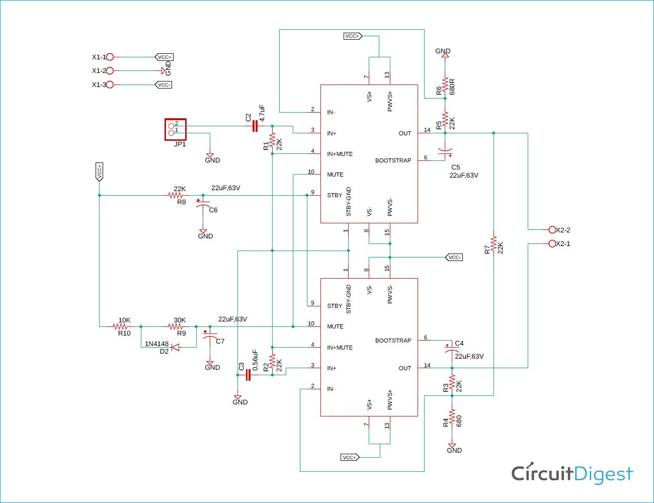
TDA7294 Based 170W High Power Audio Amplifier
The TDA7294 is a monolithic integrated circuit in Multiwatt15 package, intended for. TDA7294 Block diagram DS0013 - Rev 8 page 4/31. 4 Maximum ratings Table 1. Absolute maximum ratings. In designing a power IC, particular attention must be reserved to the circuits devoted to protection of the device

tda7294esquemaamplificadorponteestereo Circuit of dynamic amplifier using tda 7294
The TDA7294 is a monolithic integrated circuit in Multiwatt15 package, intended for use as audio class AB amplifier in Hi-Fi field applications (Home Stereo, self powered loudspeakers, Top-class TV).

Tda7294 Amplifier Circuit Diagram Pcb Wiring Diagram
This is a Class AB Audio Power Amplifier, it uses two TDA7294 Integrated Circuits, in Bridge Mode to drive one or more power speakers. The circuit provides a total output power of 170W, and this with good sound quality, powered from a symmetrical power supply.
100 Watt Power Amplifier Circuit using a Single IC TDA7294 Homemade Circuit Projects
TDA7294 is an integrated, monolithic, Class AB audio amplifier designed specifically for Hi-Fi applications. The IC has a DMOS output stage and can deliver 100W RMS into an 8Ohm speaker at +/-38V dual supply. The TDA7294 has low noise, low distortion, good ripple rejection and can be operated from a wide range of supply voltages.
